





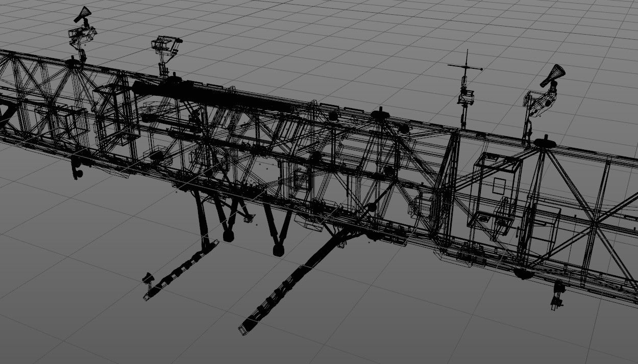
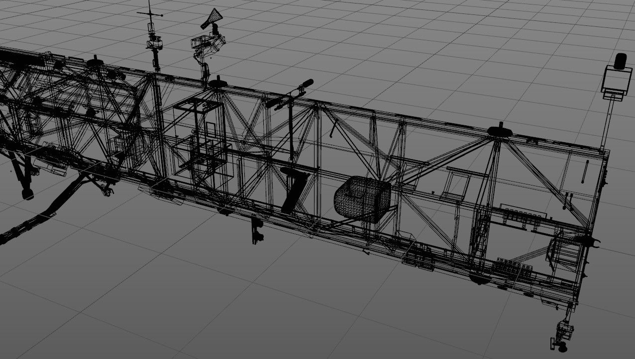
ISS - Inner Truss Segments (S0, S1, P1) 3D Model
0


0
visits

Submitted by
edobric
Specifications
- Geometrypolygonal
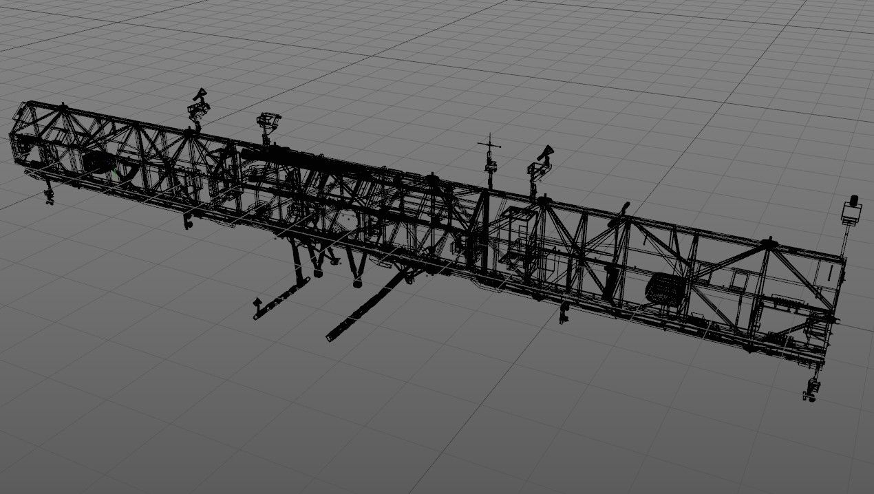
- Polygons811,413
- Vertices825,978
- TexturesYes
- RiggedYes
- AnimatedNo
- 3D Printable ReadyNo
- Game Ready (low poly)No
- UV MappedYes
- Unwrapped UVsnone
Description
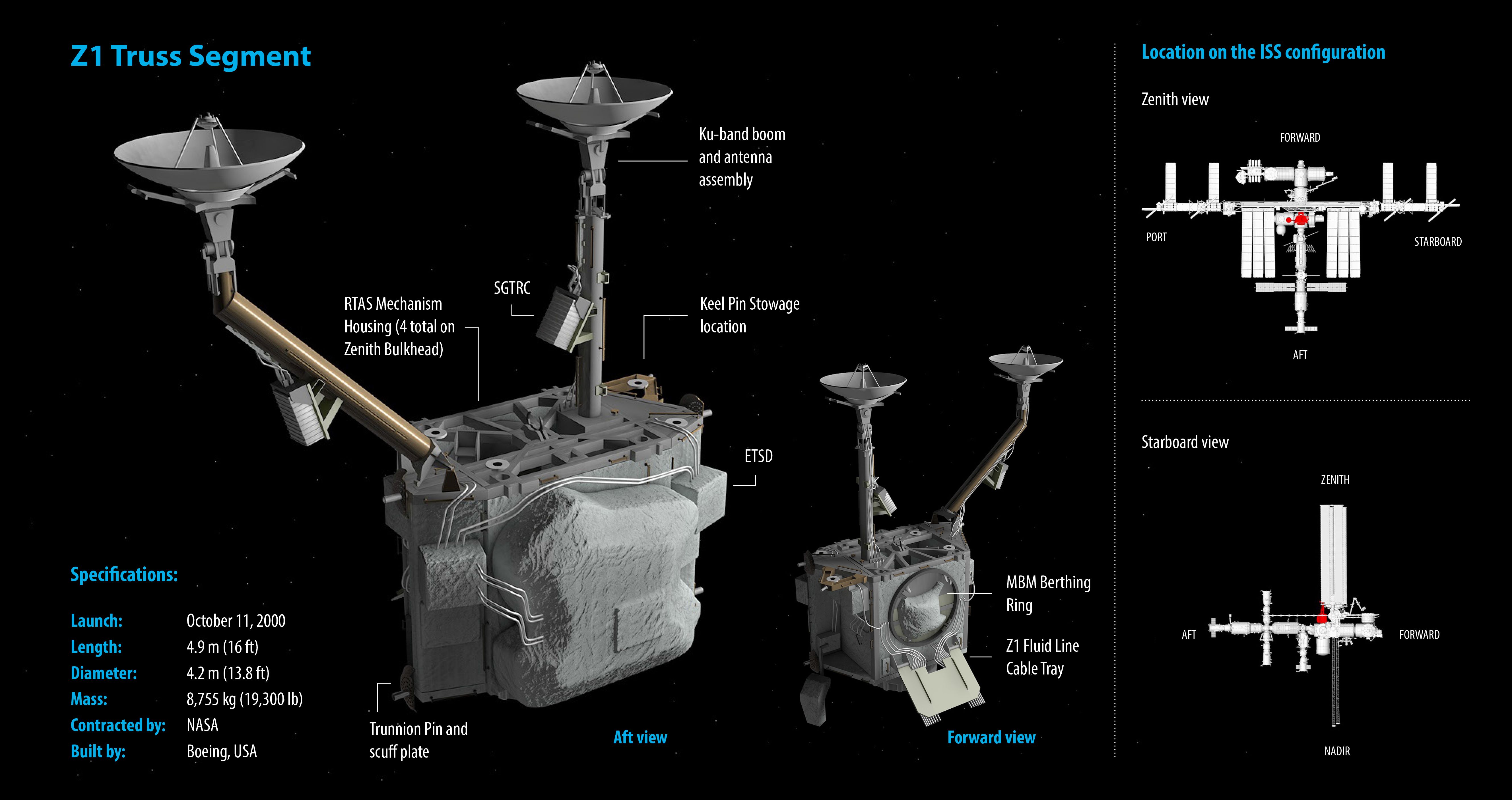
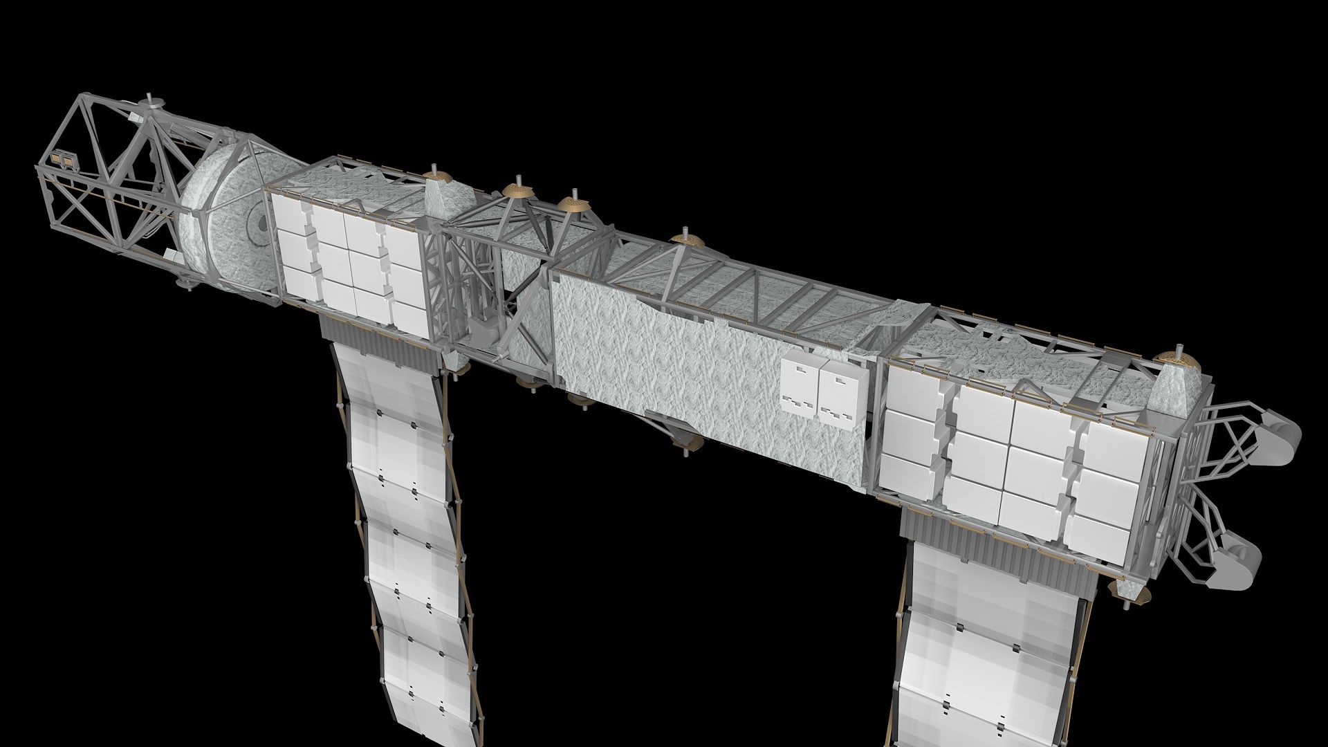
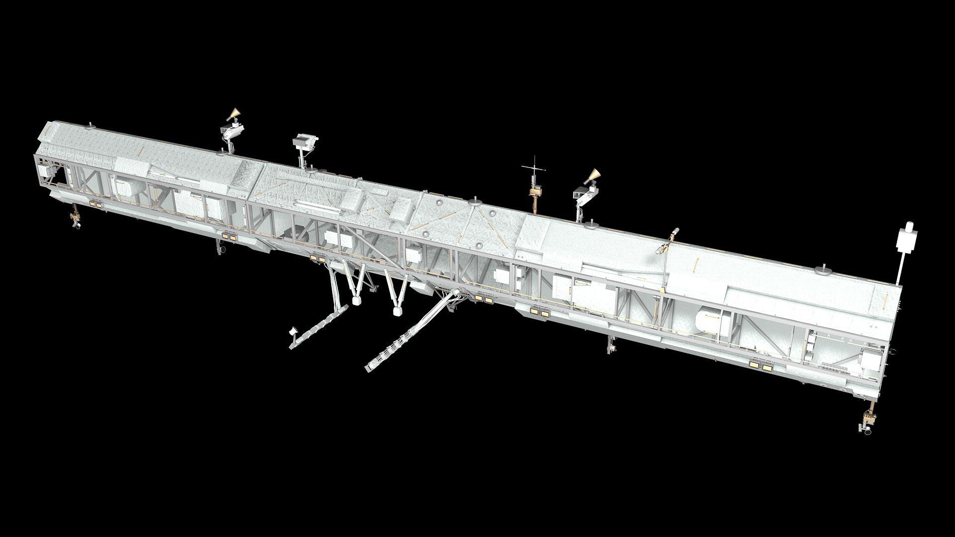
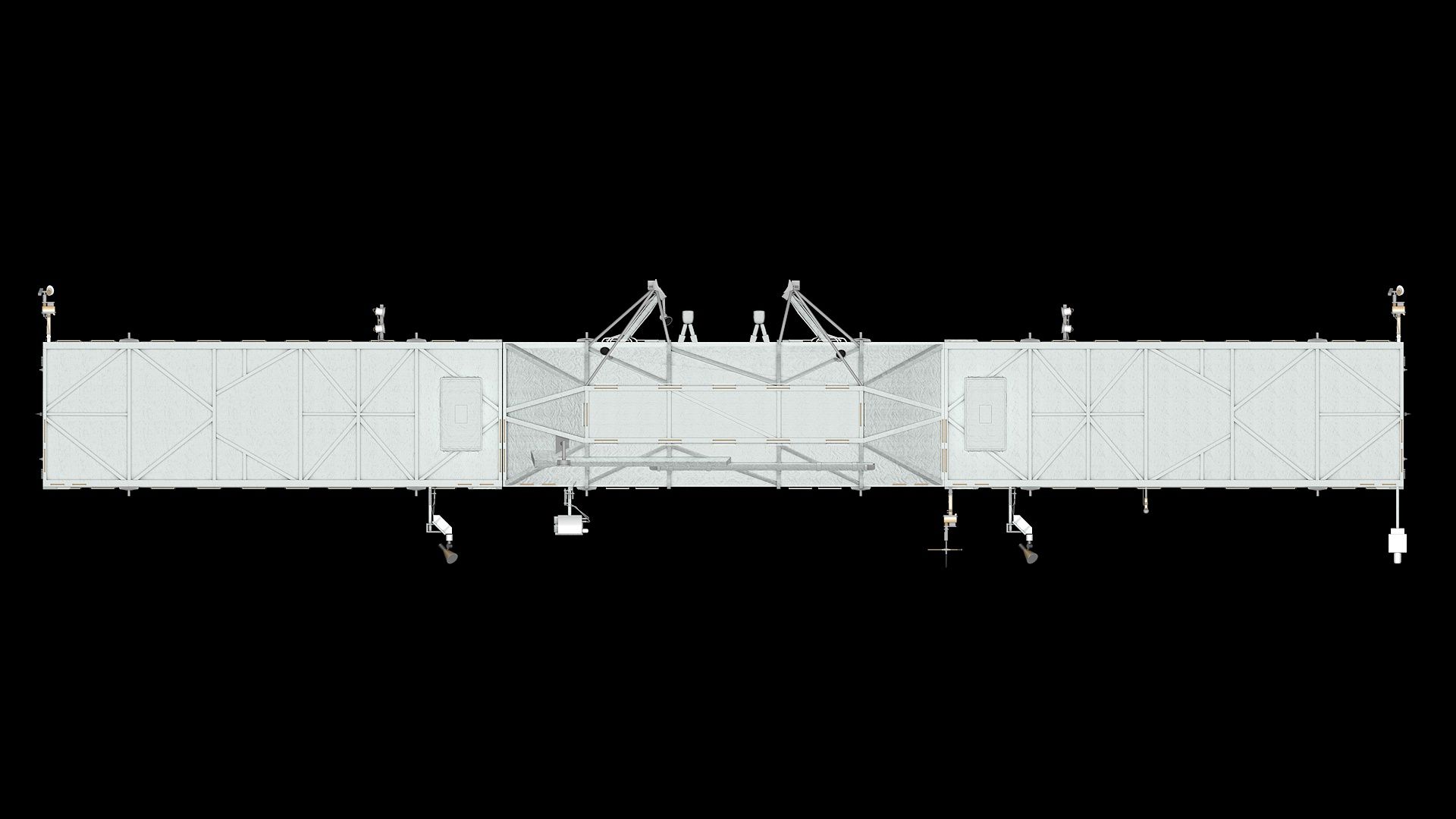
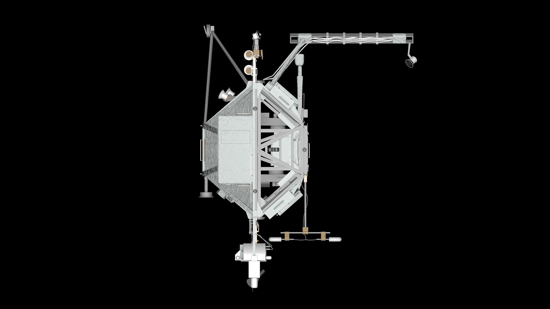
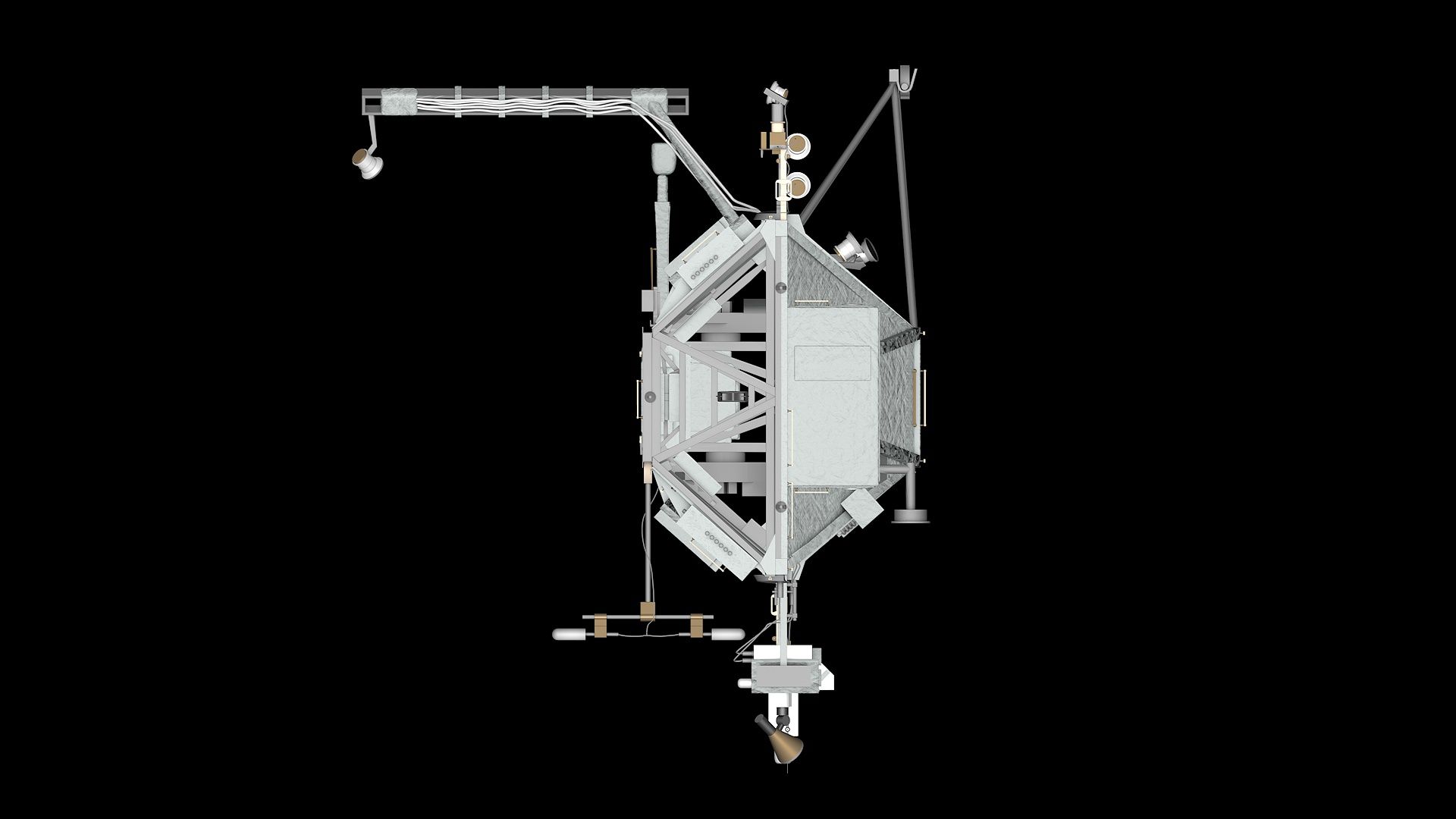
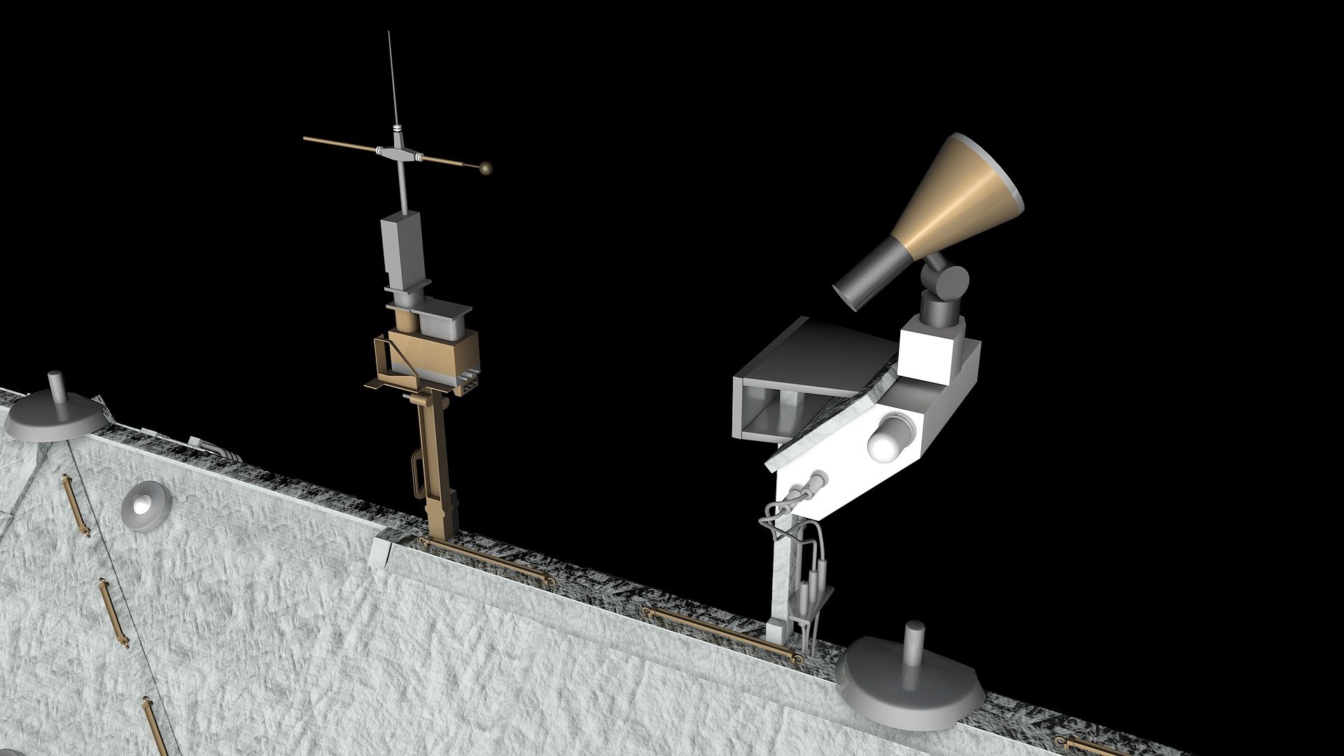
Professional 3d model of ISS (International Space Station) Inner Truss Segments - S0, S1, and P1.
Very high level of detail.
This 3d model was made with care and detail in every particular, based on real-world object.
Good overall detail with smooth mesh.
Models renders clean instantly. Quality model.
C4D used for images.
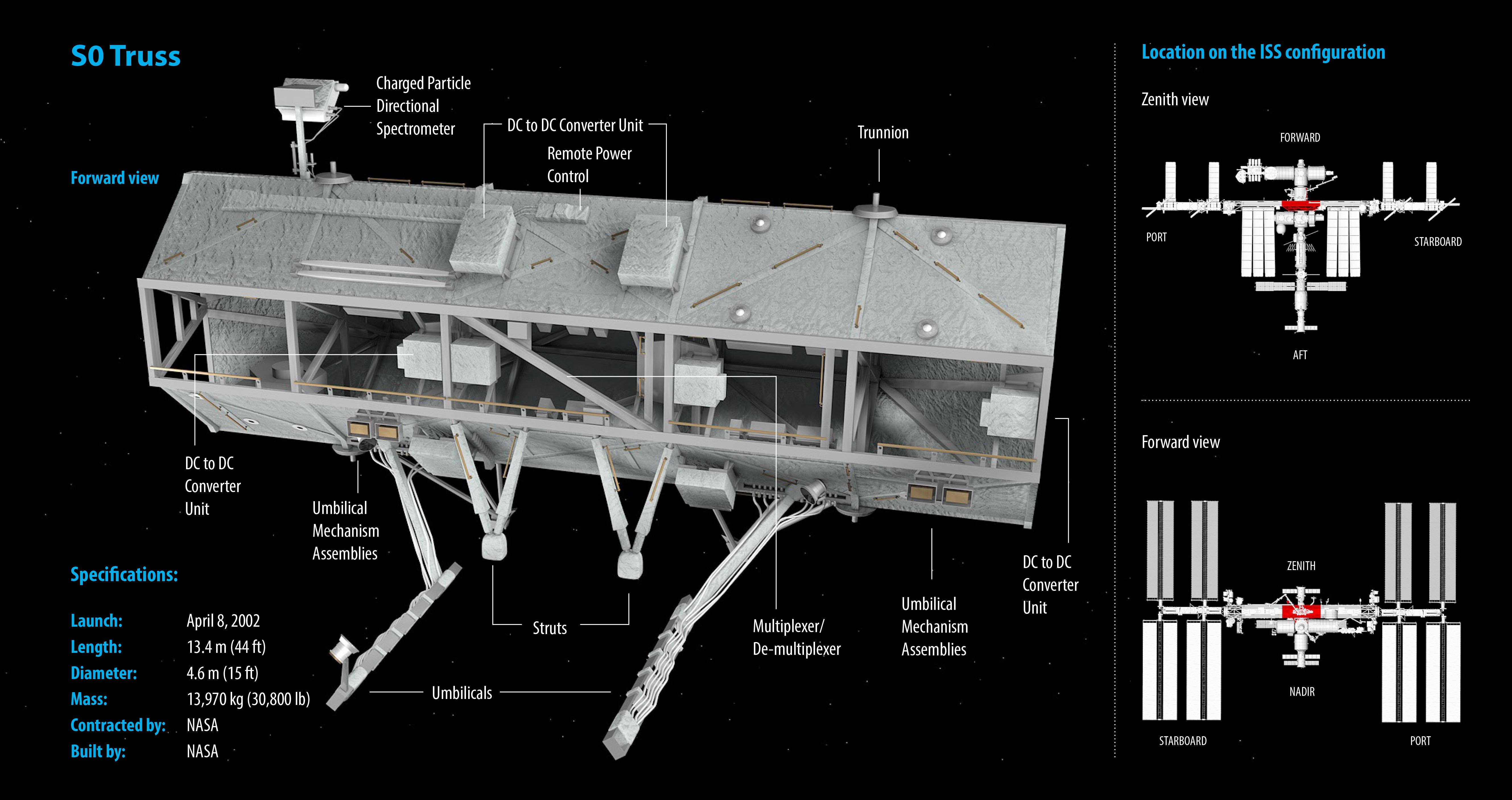
The S0 truss (also called the Center Integrated Truss Assembly Starboard 0 Truss) forms the center backbone of the Space Station. It was attached on the top of the Destiny Laboratory Module during STS-110 in April 2002. S0 is used to route power to the pressurized station modules and conduct heat away from the modules to the S1 and P1 Trusses. The S0 truss is not docked to the ISS, but is connected with four Module to Truss Structure (MTS) struts.
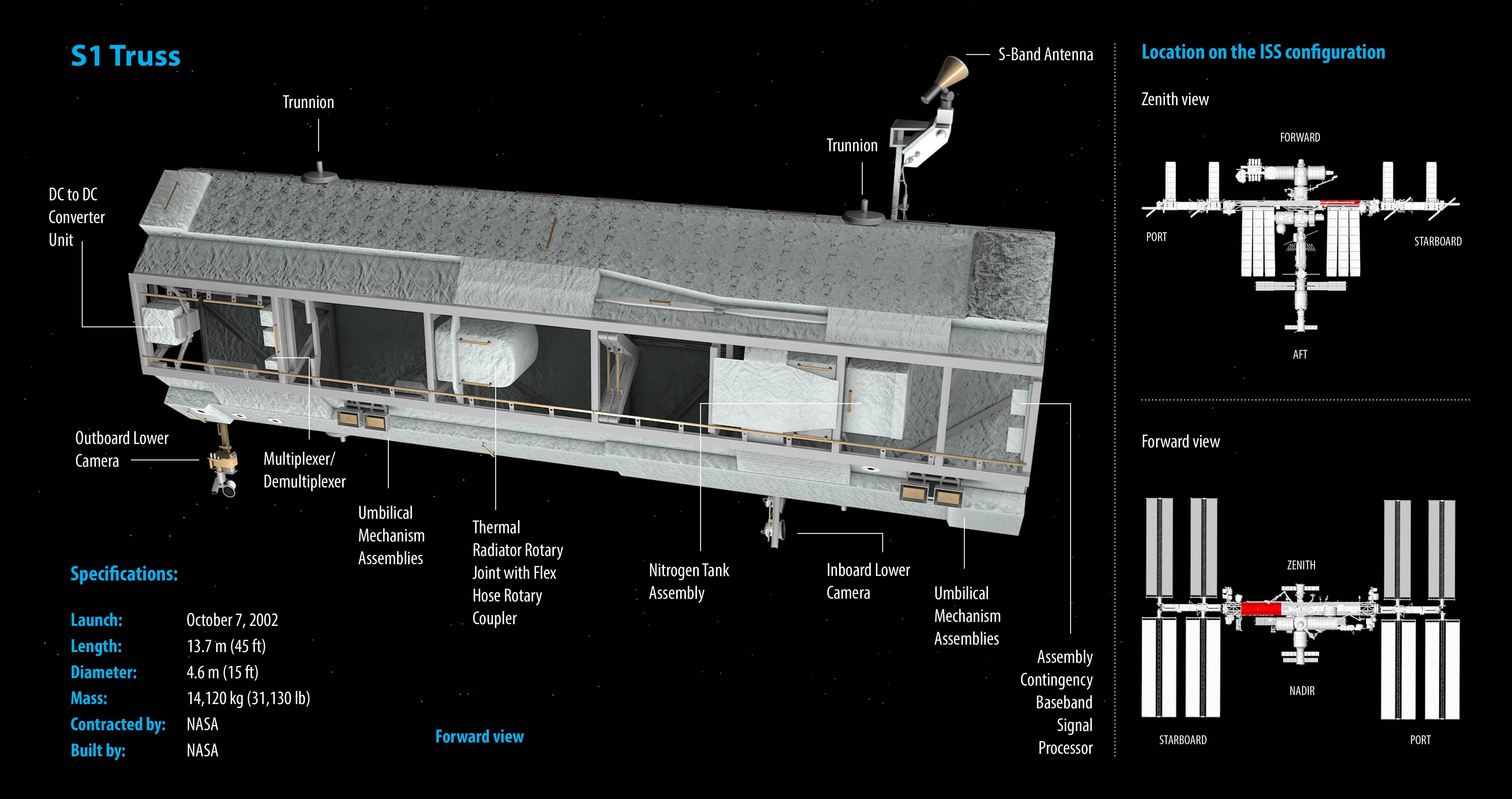
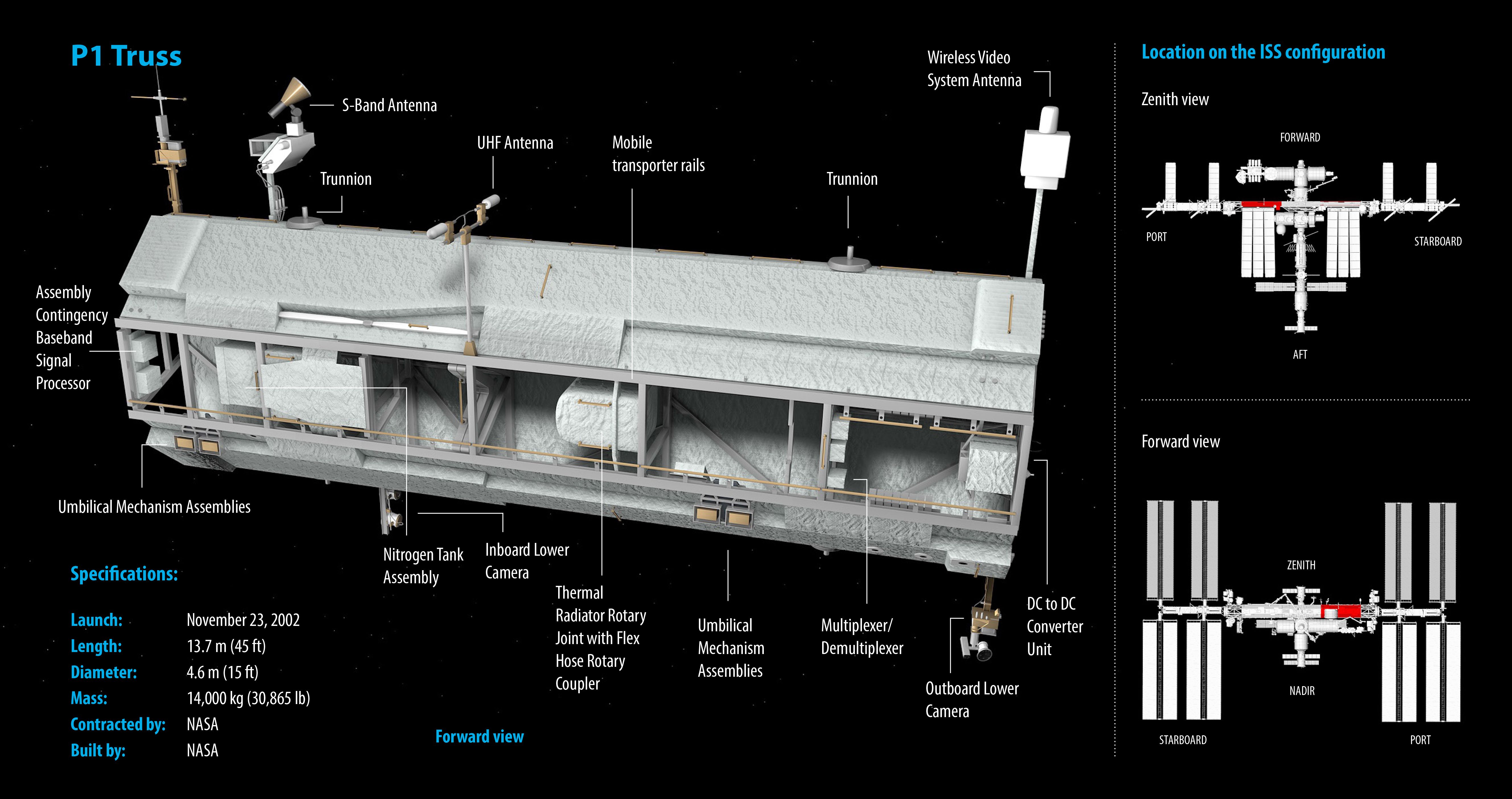
The P1 and S1 trusses (also called the Port and Starboard Side Thermal Radiator Trusses) are attached to the S0 truss, and contain carts to transport the Canadarm2 and astronauts to work sites along the space station. They each flow 290 kg (637 lb) of anhydrous ammonia through three heat rejection radiators. The S1 truss was launched on STS-112 in October 2002 and the P1 truss was launched on STS-113 in November 2002. Detailed design, test and construction of the S1 and P1 structures was conducted by McDonnell Douglas in Huntington Beach, CA. First parts were cut for the structure in 1996, and delivery of the first truss occurred in 1999.
Dec 01, 2019
date added
Mar 10, 2022
last update
Reviews
There are currently no reviews for this product.
Why not be the first one to break the ice?